| The NFPA, OISD and TAC standards require that hydrant and sprinkler distribution networks meet specific flow and pressure requirements; failing to meet fire water demand could result in grave consequences. To help circumvent potentially catastrophic events it is essential that a network analysis be performed during the design stage and before modifications are made to an existing fire water network. KYPipe provides the data necessary to ensure acceptable water flow for each line and an appropriate pressure at each node to satisfy the fire water demand. The analysis also aids in maintenance planning by analyzing pipe aging. KYPipe network analysis helps to ensure an efficient fire water network over time. |
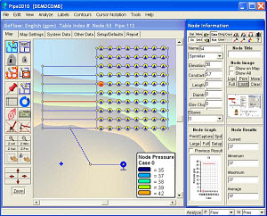
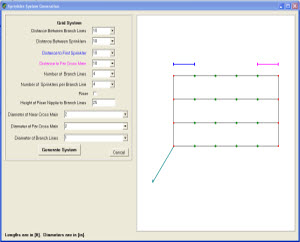
| KYPipe sprinkler and hydrant system layouts can be built with only a mouse; right-click (RC) to add pipes, left-click (LC) to select different nodes. Pipe layout grids can be used to precisely calculate pipe lengths. A number of additional features have been incorporated to simplify and accelerate the task of developing pipe system layouts and generating the corresponding data files. |
| Fire flow calculations can be made at hydrants, junctions or both. Therefore it is not necessary to include hydrants in the model to calculate fire flows. However, incorporating hydrants in KYPipe allows the user to add additional capabilities, to plot hydrant test data, calculate fire flows, and maintain accurate, detailed hydrant records. Hydrants may be emphasized using NFPA hydrant color codes. |
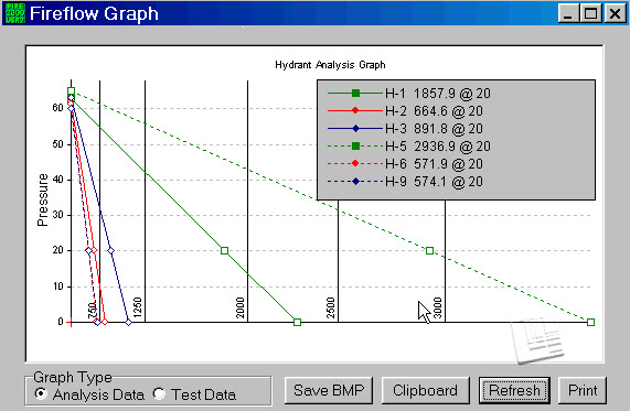
| Users can select one or more hydrants for fire flow simulation and receive calculated flow information for a variety of conditions. Some of these conditions include: determining the pumped fire flow limit to maintain a specified pressure throughout distribution system; free flow (through a hydrant nozzle into atmosphere); and fire flow through a hose and nozzle connected to a hydrant. Fire flow results are presented in a printable fire flow graph or in a detailed hydrant report. Read more about sprinkler systems here. |
| Laying Out a System | Grids for Precise Pipe Lengths (Automatically Calculated) |
 |
 |
| Hydrant Flow-Pressure Data |
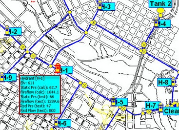
Hydrant Information Maintained by the Model |
Hydrants are labeled with pressure and flow results when an analysis is conducted. |
 |
 |
| Default Hydrant and Hose Constant / Suction Pressure at Fire Pump Calculation |
| A second calculation can also be performed to determine the maximum flow that maintains an acceptable suction pressure at a fire pump. The conventional fire flow analysis determines how much flow can be pumped out of the system and not lower the pressure in the distribution system to < 20 psi (or another specified value). This approach may overestimate the possible fire flow at locations where there is a large capacity, such as in the vicinity of a tank. This is because conventional analysis predicts fire flows so large they can’t be delivered to the pumper at an acceptable suction pressure (e.g., > 0 psi) because the losses through the hydrant and hose to the pumper are far too large. |
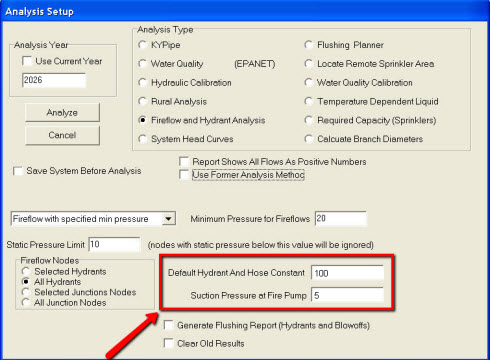 |
| Performing a second calculation: When values are entered in the fields highlighted in the image above, a second calculation generates the maximum flow value which maintains an acceptable suction pressure at the fire pump. When this is lower than the first (conventional) calculation, then the conventional approach has overestimated the potential fire flow and the second flow is a more realistic calculation of the available fire flow. |
| Hydrant Monitor Element |
|
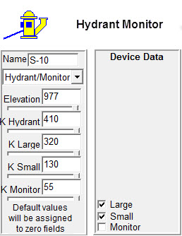
The Hydrant Monitor element allows the monitor to operate with two additional hoses connected simultaneously. The K values for the Hydrant/Monitor may be set at each individual hydrant using the Node Information Data Menu. Then the valves that are open may by selected in the Device Data Menu as shown:
|
|
|


